
Mail me
| On February 12, 2001 the diverter valve on the back panel of the M&C sample conditioning system was removed because the damned thing kept plugging with percipitated solids from the sample gas. Wayne Hanks of Petrocon told me that he "now" designs the systems without the diverter valve. | |
| The diverter valve was replaced with a "homemade fitting to connect the 3/8 inch sample line to the 1/4 inch line going into the chiller. This needs to be included in trouble shooting if and when Oxygen is high and no other source can be found. |  |

| On March 4, 2001 the rotameters showed very low flow. After replacing the primary filter the flow was still extremely low. I disconnected the sample line from the back of the sample conditioning system. Flow was still very low. Every indication pointed to a bad sample gas pump. |
| This pump is barely accessible through the top of the M&C unit. Power must be off the pump. The 1/4 inch tubing must be disconnected after labeling so it can be reconnected properly. | 
|

|
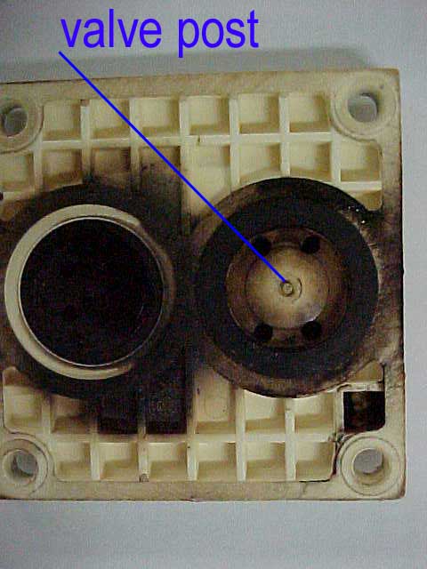
This is a side view with the valve head removed from the pump body. Before removing the head mark the orientation so that the head can be returned to its original orientation. The pump head can be fairly warm so do not be startled by the heat and jerk away and break something |
| The head separates into two unequal portions. Between the two parts are two soft rubbery flap valves. These valves act as check valves. Be careful so that these do not get lost. On a flat surface gentlely scrub the black solids off of the surfaces with water and then methanol. You may notice a raised nipple in the center of the valve heads. These are to locate the flaps. Use a thin layer of moisture to hold the flaps in place until the two portions are realigned. | 
|
|

|
| Notice the black cirle with the white center. This is the flap. The other side of this pump head part has four holes like a salt shaker. All solid particle should be scrubbed of the surfaces and the flap cleaned. | The picture above is one of the flappers. These, barring physical destruction, should have a long lifetime. There are spares in the supply box in the bottom of the CEM. Any parts used must be replaced when used and the repairs documented in the "calibration book". |
| May 25, 2001 The gas sample pumps continually lose flow and have all shown a sticky black "goo" coating the flaps. I adapted an 11 centimeter filter holder, previously used for stack sampling, between the gas chiller and the moisture sensor. Had to use rubber rolled tubing to seal around the plastic tubing. Since installing the GFA filter the front mounted "Balston" type filer and glass bowl have collected a lot of water. I don't know the cause of the condensation. The 11 cm filter assembly was removed August 2001. The boiler had sprung a tube leak and the liquid was weak sulfuric. |
 View from panel side of SCS |
 View from Boiler Room Door |
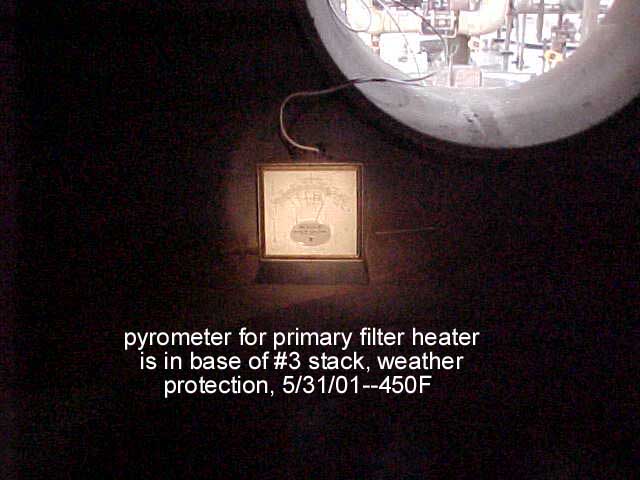
I have installed a K-type thermocouple between the heaters and the filter holder body of the primary filter assembly and ran wires down to grade so that I can check the temperature of the filter without having to climb ladders. The pyrometer is inside the base of the #3 stack to protect the instrument from the weather. The reading has stabilized at 450 degrees F. |
| After struggling with the gas sample pump buried in the M&C box I decided to move it entirely out of the box for ease of approach. On May 1, 2002 I mounted a new pump on a piece of aluminum stock I had scrounged. The stock piece is bolted to the strut by one backed bolt and rests on the right hand side of the M&C box. | 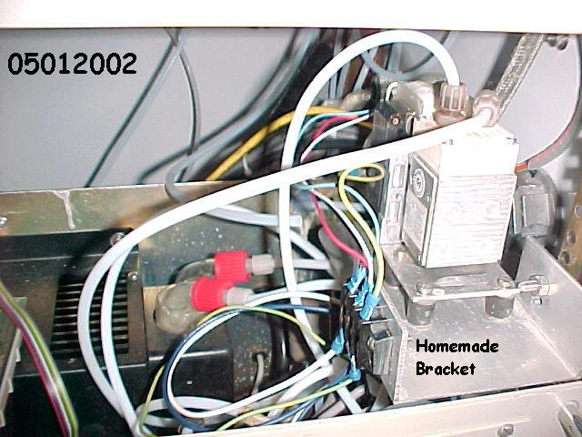 |
 |
Notice the fan. This can be quite startling if you inadvertently contact it while bumbling around in cabinet. The fan is plastic and not very likely to hurt. |
| Note the exposed terminal screws. This is done for illustration. The connections will be safely covered. |  |
Return to Index