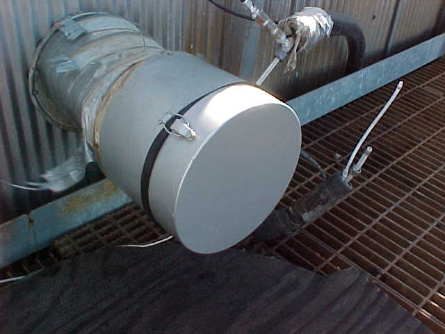
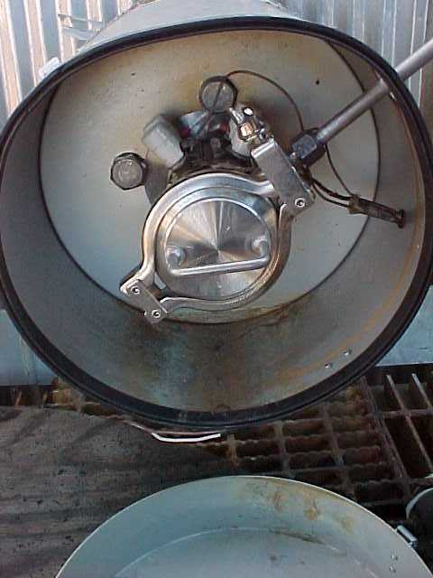
Check on the condition of the stainless steel primary filter and fitting by climbing the two flights of ladders by C-1, and coming to the housing covering the end portion of the probe. Remember to close the devices at the ladder openings. Remove the filter assembly cover (which is probably held on with tape), and you will see the primary filter housing and stainless section of line. For the following steps you shall wear a minimum of a slicker suit (top and bottom), chemical gloves, face shield, and goggles (a full face respirator may be worn in lieu of face shield and goggles). Disconnect this line at the tee. You should feel the hot air blowing from the end. If you do not disconnect this sub-assembly from the filter housing. Examine the sub-assembly for pluggage. You should obviously be able to see right through it. Corrosion and grime may be evident on the outside of the tubing near the nuts. Replace if needed.

Heated sample line replaced December 2000 by Tracer Industries sales rep Jim Dennington. Inspect the line occasionally to assure sags have not developed. Use heavy gauge wire to support sagging sections.

The filter housing assembly is heated and should be above 340°F. If not turn off power and troubleshoot heaters.
If the sub-assembly is open and there is no flow out of the filter housing the primary filter needs to be changed or the sample probe needs to be cleared. For the following steps you shall wear a minimum of a slicker suit (top and bottom), chemical gloves, face shield, and goggles (a full face respirator may be worn in lieu of face shield and goggles). Stay out of the direct center line of the filter holder assembly to avoid very hot flue gas with high levels of dust and SO2. Wear gloves to protect hands from the heat.
|
Loosen the wing nut and open clamp. Slightly twist the handle and remove filter holder. |
|
Clogged filter |
Plugged Probe |
|
A large volume of hot exhaust gas should be blowing from the sample probe opening. Remove the old filter from its holder and replace with a new one. Be sure the sealing gaskets are in place or a proper seal cannot be achieved. The Filters are Horiba part #384270. There are 12 in a box and a box is $ 393.00 as of 1/2001. Filter caps # 384273 are 10/box @ $78.00/box, The caps can be reused with care. |
If it appears the probe is plugged (low or no flow) the "high tech" probe solids removal device will be required. This special item is a 4 foot piece of 1/4 inch SS tubing hanging from the grate near the filter housing. Insert the tool into the probe opening and with twirling pushing motion ream out the sample probe. There will be a lot of hot solids and gas blown or ejected from the probe when it is finally cleared. Replace the stainless steel filter. |
If all the checks above showed good flow then the sample line needs to be washed. If you are going to wash the sample line, do not reconnect the system. Turn off the power to the heated sample line with the switch in the controller box. Go to the cylinder area across from the CEM and find the adapter for attaching to a plant water line. You will also need the long section of 1/4" plastic tubing.
|
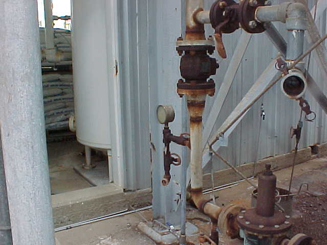
Adjust the flow of water thru the ½ inch pipe to ¼ inch tubing adapter so that the water hits the concrete about 2 feet from the fitting. Hook up one end of the water line at the valve located behind the small building containing softeners R210 and 211, and then go back to the analyzer to get it ready for hookup. Disconnect the 3/8" sample line from the back of the analyzer and connect it to the the water line with the supplied adapter. Flush with water for approximately ten minutes. |

Note the water line connection below the gauge in the center of the photo. |
Afterwards, turn off water and remove water line from plant fitting and attach the nitrogen line coming from the analyzer to purge and blow out the remaining water in the line. This is done by disconnecting the nitrogen line at the point where it goes into the equipment enclosure at the point labeled "enclosure purge". Be sure to remove the line after the valve so you can control the flow of nitrogen through the line. Allow the line to purge for at least ten minutes once you do not visibly see water coming out of the line at the top. Once this is done, restore power to the sample line, disconnect all fittings and reassemble the analyzer sample line to its original state only after the heated sample line has reached 180°F.
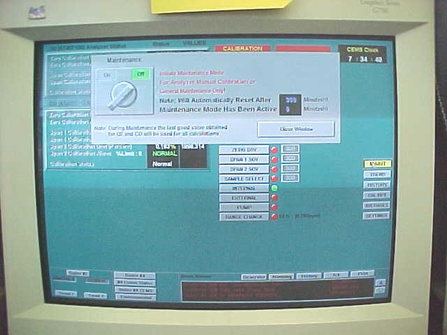
Next, go back to the Evaps control room and turn off the maintenance function. Do this by just clicking on the "virtual" switch and it will go from "on" to "off". You next do the calibration by clicking on the "calibrate" "virtual" switch. The system will go into the calibrate mode and let you know when it is finished from the times shown for each calibration check. The system will also let you know if everything is NORMAL.
|
Once you have completed the above series of steps, be sure to document the procedure in the log book located on top of the analyzer in the enclosure. Record the maintenance time to the nearest ¼ hour. |

|
Return to Index


